
Adjustable EUC pedal concept
Long-distance EUC riders move their feet for a reason. After two hours on a heavy wheel, stance is not a detail - it is circulation, braking leverage, knee load, balance point, and how much attention the machine steals from the ride.
This concept asks a narrow question: could an EUC pedal adjust toe and heel length independently while staying structurally honest enough for a primary safety part?
The answer is not “yes” yet. The answer is: maybe, but only if the sliding sections never become the weak link, the adjustment mechanism cannot drift, and contamination does not turn the pedal into expensive seized hardware.

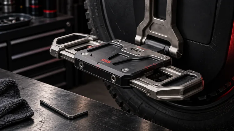
A mounted concept view: two adjustable ends, one fixed structural center, and side-access hex adjustment.
Visual reference
In the reference ride, the front of the shoe sits beyond the pedal edge. That does not automatically prove the pedal is wrong - some riders like toe overhang - but it shows the problem this concept is trying to investigate: support length, stance bias, and leverage are not always tuned to the rider, shoe, and wheel.

The ergonomic trigger: a real riding stance where the shoe toe extends beyond the pedal edge.
Problem
Most EUC pedals are fixed plates. You can change pads, shoe position, pedal angle, grip, spikes, and sometimes the whole pedal, but the platform itself usually has one footprint.
That works for short rides and predictable use. It gets less ideal when a rider is doing long touring, mixed terrain, steep braking, seated-to-standing transitions, or several hours on a 40-60 kg (88-132 lbs) wheel.
The rider may want:
- More toe support for acceleration and pad engagement
- More heel support for braking and descending
- A shorter platform for technical maneuvering
- A longer platform for relaxed cruising
- A slightly shifted stance without changing pads or removing hardware
The hard part is that pedals are safety-critical. A clever adjustment mechanism is worthless if it adds flex, play, position drift, contamination problems, or fatigue cracks.
Current state
Today the usual solutions are blunt:
- Buy a larger pedal
- Buy a smaller pedal
- Add grip plates or spikes
- Move power pads
- Change shoe position manually
- Accept that the wheel feels different after your feet get tired
Aftermarket pedals already improve support and grip, but they do not usually solve stance-length tuning. Some riders compensate by changing foot position during the ride. That works, but it is not the same as changing the platform geometry.
The current EUC market also tends to solve rider comfort by adding more mass and more surface area. That is simple, but not elegant. A 55 kg (121 lbs) GT wheel does not need every answer to be “make the part bigger.”
Proposed concept
The pedal is a three-part longitudinal assembly.
A fixed central body bolts to the pedal hanger and carries the hinge, hinge pin, and full structural load path. A front toe section and a rear heel section slide fore and aft inside that body on two rigid low-profile rails.
Each sliding section is driven by its own lead screw. Each lead screw is turned by a self-locking worm gear pair. The worm shaft ends in a 4 mm hex socket on the outboard side face, so the rider can adjust the pedal with a normal Allen key while the pedal stays bolted to the wheel.
Target travel:
- Toe section: about 25 mm forward
- Heel section: about 25 mm rearward
- Adjustment: continuous, not indexed
- Tool: 4 mm Allen key
- Use case: garage setup, trail-side tuning, long-ride stance adjustment
The core idea is not “motorized pedal” or “quick release pedal.” It is slower and more mechanical on purpose: a tool-adjusted, self-locking, load-path-first pedal for riders who care more about stability than gimmicks.

The adjustment range should be meaningful, but still bounded by hard mechanical end stops.
Two architecture paths
There are two credible ways to interpret this idea.
Path A: independent toe and heel extension. This is the main concept in this article. The toe section and heel section move separately, so the rider can tune actual platform geometry. More toe support can help acceleration and pad engagement. More heel support can help braking, descending, and long-distance comfort. The rider can also keep one end compact while extending the other.
That is the more interesting R&D path, but also the harder one. It needs two drive mechanisms, two sliding interfaces, more sealing, more wear control, and stricter play management. It gives the rider more adjustment, but it creates more ways for a safety-critical part to become loose, dirty, or annoying.
Path B: sliding fixed-length platform. The whole pedal platform keeps one fixed length and slides forward or rearward as a single unit relative to the hanger. One screw, one lock, one sliding body. This does not change foot support length. It changes stance bias: more toe-forward, more heel-forward, or more centered.
That version is less ambitious, but it may be the better first prototype. It is simpler, stiffer, easier to seal, easier to machine, and easier to test. It can answer an important rider question before the harder mechanism exists: does adjustable pedal position actually improve control and comfort enough to justify the complexity?
The 555 reading is simple: Path A is the vision, Path B is the research mule. If Path B does not prove real rider value, Path A probably does not deserve the extra mechanical risk.

Path A changes platform geometry. Path B shifts stance bias with a simpler fixed-length sliding platform.
Simpler OEM path
There is also a third path that is less romantic, but probably closer to production: do not make the pedal adjustable. Make the pedal mount multi-position.
On wheels where the pedal hanger is already a separate bolt-on part, a manufacturer could add fixed mounting positions or alternative hanger geometry: forward, neutral, rearward, or height-specific. The rider would not tune the pedal every ride. They would choose a stance during setup, bolt it down, and keep the structural part simple.
That matters because the research signal already points in this direction. LeaperKim/Veteran platforms use replaceable pedal hangers across models such as Patton, Lynx, Sherman L, Lynx-S, and Oryx. The Lynx-S is marketed with adjustable pedal height positions. King Song’s S22 is the clearest public example of a factory adjustable hanger architecture being used by riders to move pedal position forward, though the exact offset is not manufacturer-documented. Aftermarket parts go even further: Hou Ningning lists Lynx/Sherman L CNC hangers with -10 mm / -22 mm settings, while Beidou QX sells fixed lowering brackets for Lynx.
The important distinction is this: height, fore/aft position, and pedal angle are different problems. Most existing products change height or angle. True fore/aft adjustment is less common. So the article should not claim that every replaceable hanger solves toe and heel reach. It only proves that the hanger interface is already a practical place to experiment.
For an OEM, the staged path could be:
- Fixed multi-position hanger first
- Sliding fixed-length platform second
- Independent toe and heel extension only if the simpler versions prove rider value
That may be the most realistic version of the idea. A few well-placed mounting holes or hanger variants could solve part of the stance problem without adding small moving parts below the axle.
Internal mechanism
Inside each half of the central body:

The mechanism is intentionally mechanical: rails carry structure, screws move sections, worm drives lock position.
- One 8 mm stainless lead screw, likely M8x1.25 or a 2 mm lead trapezoidal thread
- A flanged bronze or PTFE-lined bushing supporting the inboard end of the screw
- A single-start steel worm on a short transverse shaft
- A 4 mm hex socket broached into the outboard end of the worm shaft
- A bronze worm wheel keyed and pinned to the inboard end of the lead screw
- A split anti-backlash nut pressed into the sliding section
- A small compression spring preloading the nut halves against opposite thread flanks
A single-start worm with a 20-24 tooth worm wheel gives roughly 20:1 reduction. That keeps the worm lead angle well below the friction angle, which is what makes the drive self-locking. The screw should not be able to back-drive the worm.
That ratio has a cost. With 20:1 reduction, adjustment can become painfully slow: roughly one Allen-key turn per 0.1 mm of travel, depending on screw lead and gear geometry. Full 25 mm travel could take a few hundred turns.
Dropping closer to 8:1 makes adjustment much faster, but moves the design closer to the self-locking boundary. Vibration, contamination, lubrication, wear, and temperature all matter there. This is one of the unresolved trade-offs in the concept.
Load path
This is the part that decides whether the concept deserves a prototype.
Rider load enters through the traction plate, into the sliding section’s top skin, and then into two full-length rail tongues machined into the section side walls. Those tongues run in matching dovetail or T-slot grooves in the central body.
Vertical load, side load, and pitch moment react through the rail flanks and the vertical overlap between the sliding section and the central body. They do not go through the lead screw, worm wheel, worm teeth, or anti-backlash nut.
The screw should only see the axial force needed to move the section against friction, plus small residual axial load from nut clearance. The nut pocket should therefore have slight radial float, roughly 0.15-0.25 mm, so the nut cannot become a structural member if the rails deflect.
Minimum overlap between each sliding section and the body should be around 45-50 mm at full extension. That gives an overlap-to-overhang ratio near 2:1. Below that, bearing pressure and rail-root stress rise fast.
The central body length is therefore set by overlap, not by visual footprint. From the body, the load passes into the hinge boss, hinge pin, and pedal hanger like a conventional EUC pedal.
Play, locking, and position drift
Four mechanisms work together. No single one is enough.
Gib strip. One rail groove carries a replaceable tapered gib strip preloaded by three M3 stainless grub screws. This sets running clearance around 0.02-0.05 mm and allows wear to be taken up over the pedal’s life.
Self-locking worm. A single-start worm with a low lead angle blocks back-drive through static friction. This is the primary anti-drift feature.
Anti-backlash nut. The split nut removes axial lash so the sliding section does not shuttle under alternating braking and accelerating load. That shuttle is where “clicking adjustable hardware” usually begins.
Worm shaft friction. A wave washer or similar preload on the worm shaft adds breakaway torque and helps stop vibration creep.
Positive end stops should be machined shoulders. A stop tab on each sliding section runs into a matching land in the central body. The screw must never be the end stop. Bottoming a screw under impact is how a small mechanism becomes a structural failure.
Why it might work
The concept has a credible path because the adjustment mechanism is not asked to carry rider load.
The rails carry load. The central body carries the hinge structure. The screw moves the section. The worm locks position. That separation matters.
It also solves a real rider problem without requiring electronics, motors, firmware, batteries, or app control. A 4 mm Allen key is boring in the best possible way. It is easy to carry, easy to understand, and hard to brick.
Independent toe and heel adjustment is the interesting part. A rider could extend the toe for pad engagement without making the heel feel clumsy. Or extend the heel for braking without pushing the whole foot position forward.
For touring riders, the value is not constant adjustment every five minutes. The value is having a pedal that can be tuned for body, shoe, wheel, pads, route, and fatigue pattern without replacing the whole part.
System architecture
The concept breaks into six functional zones:
Central body. Structural core, hinge boss, rail grooves, worm shafts, screw supports, end-stop lands.
Toe sliding section. Forward support, rail tongues, top plate, traction pins, nut pocket, front wiper interface.
Heel sliding section. Rear support, rail tongues, top plate, traction pins, nut pocket, rear wiper interface.
Drive modules. Lead screw, worm, worm wheel, bushings, anti-backlash nut, preload spring, hex socket, dust plug.
Wear and sealing parts. Replaceable gib strips, wiper seals, socket dust plugs, top plates, screws.
Hinge interface. Hinge pin, hanger contact geometry, fold clearance, pedal angle, and the load transfer into the wheel.
Preliminary materials:
- Main structural parts: 7075-T6 aluminium, hard anodized
- Top plates: 7075-T6 or 6061 aluminium, replaceable
- Lead screws and fasteners: A4 stainless
- Worms: case-hardened steel
- Worm wheels: aluminium bronze
- Bushings: bronze or PTFE-lined
- Wipers: NBR or polyurethane
Expected mass is not small. A fixed 7075 pedal of similar footprint might land around 220-280 g. This concept likely lands around 380-480 g per side depending on wall thickness, rail geometry, and hardware. That adds about 250-400 g total to the wheel, all of it low and unsprung.
Risks and trade-offs
Weight. This is heavier than a simple pedal. The mechanism, rails, bushings, worm gears, screws, and overlap requirement all add mass.
Stiffness. A three-piece sliding pedal will never be as stiff as a monolithic plate. Full extension is the worst case. If the pedal feels flexible under braking, the concept fails even if it survives.
Adjustment speed. 20:1 is safer for self-locking but slow. 8:1 is faster but less conservative. This ratio needs real bench testing, not spreadsheet confidence.
Contamination. Pedal rails live below the axle, near the tire, directly in the spray zone. Sand, mud, salt, water, and metal dust are the most likely real-world killers.
Fatigue. Dovetail and T-slot grooves create internal corners. Those corners see millions of cycles and impact spikes above static rider weight. Rail roots need generous radii and testing after anodizing.
Cost. Multi-axis CNC, hard anodizing, bronze, stainless, bushings, wipers, and small gear parts make this a low-volume premium part.
Safety perception. Riders must trust pedals. If the mechanism looks clever but fragile, many experienced riders will reject it before testing. That skepticism is healthy.
Implementation levels
Level 1: Bench mechanism. Build one drive module and one rail-and-gib coupon. Measure adjustment torque, backlash, running clearance, contamination sensitivity, and turns-to-travel.
Level 2: Static pedal prototype. Build a full pedal in 6061 for fit, fold clearance, shoe feel, grip plate design, and static load testing. Do not ride it yet.
Level 3: Structural prototype. Build an anodized 7075 version with final-ish rail geometry and end stops. Test static load, overload, hinge pin shear, and full-extension stiffness.
Level 4: Fatigue and contamination prototype. Run cyclic loading, mud and salt exposure, freeze-thaw, position drift testing, and teardown inspection.
Level 5: Manufacturer-grade design. Only after the above: production tolerances, sealing strategy, service kit, replacement wear parts, liability review, and rider documentation.
What needs testing
The first calculation pass should cover:
- Static and dynamic vertical load at full extension
- A design case of at least 3-4x rider weight per pedal for curb strikes and landings
- Rail bearing pressure and contact stress on the dovetail or T-slot flanks
- Bending and torsion of each sliding section at maximum extension
- Worm lead angle versus friction angle across wet, dry, cold, warm, clean, and contaminated states
- Thread shear and buckling on the lead screw
- Hinge pin shear
- Hanger-interface bolt preload and local contact stress
Prototype testing should start smaller than a whole pedal. First build a rail-and-gib test coupon. Then build a drive-module mock-up. Only after adjustment torque, backlash, and contamination behavior look sane should the full pedal exist.
Fatigue testing should run at least 10^6 cycles at service load with overload spikes, with the sliding section held at full extension. Test anodized parts, not bare aluminium, because anodizing can reduce fatigue life.
Environmental testing matters as much as strength:
- Mud ingress
- Sand ingress
- Salt slurry
- Freeze-thaw
- Pressure washing abuse
- Torque-to-adjust after contamination
- Galvanic corrosion between stainless, aluminium, and bronze
The most safety-relevant field test is position drift. Ride vibration should be measured as actual section movement over distance. A pedal section that creeps outward without the rider noticing is not an inconvenience. It changes the rider’s balance point mid-ride.
Who this helps
This is not for a beginner commuter wheel.
It makes the most sense for:
- Long-distance riders who change stance over hours
- Heavy-wheel riders on 40-60 kg (88-132 lbs) machines
- Riders tuning toe support separately from heel support
- Riders who alternate between aggressive braking and relaxed cruising
- Touring setups where pads, shoes, luggage, and fatigue change the ideal stance
- Prototype builders and manufacturers exploring high-end ergonomic hardware
It makes less sense for:
- Lightweight city wheels
- Riders who want the simplest possible pedal
- Mud-heavy riding unless sealing proves excellent
- Jump-heavy use unless fatigue testing is brutal and passed
- Anyone expecting a cheap aftermarket part
555 take
This is worth prototyping, but only as a serious engineering part, not as a clever accessory.
The concept has one strong idea: independent toe and heel adjustment with a conventional structural load path. That could give long-distance riders real stance control without moving pads or swapping pedals.
The unresolved question is not whether the mechanism can move. It can. The question is whether it can stay stiff, clean enough, locked, fatigue-resistant, and trustworthy after thousands of kilometers below an EUC axle.
Until that is proven, this is an R&D concept, not riding hardware.